Rewriting my grid parts page #
If you've followed my work you know I'm a fan of grids. I had a page I wrote in 2006 that I decided to update. Those were the days before html5, and even before SVG was reliable in browsers, so I had made images using some Ruby code to generate SVG, and then ImageMagick to turn SVG into PNG. If I'm going to update this page, what might I want? I made a list of possibilities:
- Change of focus. The old page spends a lot of time talking about the properties of grids in the abstract, and how different grid types relate to each other. When I visit the page for my own needs, I don't care about that. What I do want to see is the formulas. I use this page as a reference. I want to change it to make the formulas the main focus of the page.
- Interactivity. I could make all the diagrams interactive. That's what people expect from me, after all!
- High resolution diagrams. We're not living with 800⨉600 desktop monitors anymore. With "HiDPI" screens including 4K, I wanted to use SVG everywhere so that the diagrams are sharp.
- Put coordinates into the diagrams instead of only off on the side.
- Make the relationship diagrams for all three grid types. On the original page I have diagrams only for squares.
- Animations showing how square grids relate to triangle and hexagon grids.
- Animation showing how square grids relate to isometric grids (which are really isometric views of a square grid).
- More algorithms including distances, to screen coordinates, from screen coordinates.
- Sample code generation, so that you could select a programming language and see sample code in your favorite language.
Labels: grids
Square tiling of a sphere, part 3/3 #
In the previous post I described how I learned about the cube/sphere geometry so that I could put a square grid on a sphere. I ended up spending too much time on that, because it turns out the mapping from cube to sphere wasn't as useful as I had thought. This happens to me sometimes, where I find something fascinating, spend a lot of time on it, and it turns out to be not that important.
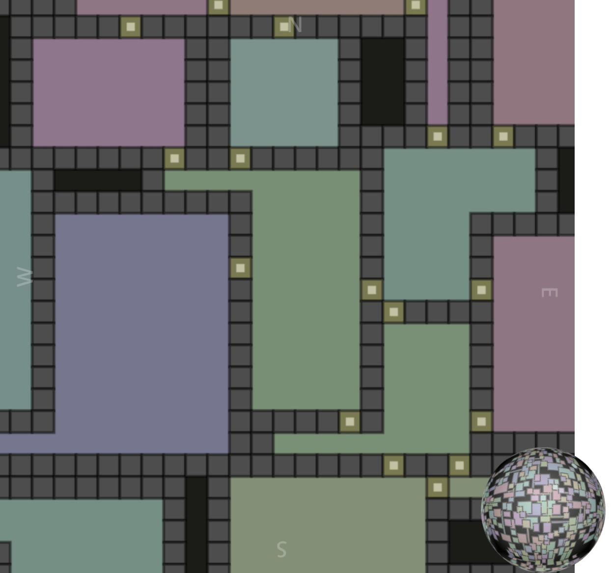
As the final step in learning how to work with square tiles on a sphere, I wanted to make something on the sphere. I decided to make a dungeon map.
Square tiling of a sphere, part 2/3 #
In the previous post I described how I learned about HEALPix because I wanted to try covering a sphere with square tiles for a game map. During that exploration I realized that HEALPix with 12 square regions is similar to cubes with 6 square regions, but HEALPix has some nice properties for numerical calculations such as spherical harmonics. I don't need those properties. Instead, I am looking for something that's simpler to program, so I explored cubes.
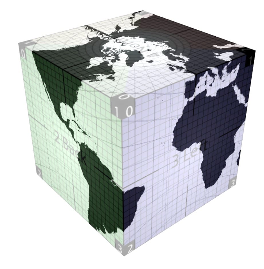
The goal is the same: I want to play a game on a flat top-down tile map (roguelikes, Dwarf Fortress, Factorio, etc.), but these games have one of three approaches to the map:
Square tiling of a sphere, part 1/3 #
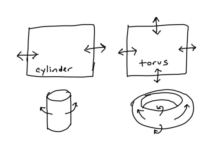
I almost always work on 2D game maps, but occasionally I get intrigued by planetary maps. I'd like to make a planet that uses a grid. The topology of a sphere requires a few things:
- Moving east or west you eventually wrap around the world → easy
- Moving north/south you eventually reach a pole, and then all directions are south/north → medium
- Wrapping around the world east/west is shorter near the poles than near the equator → hard
Tiles and edges #
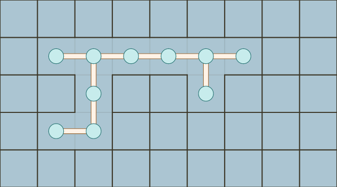
Last winter I was playing Factorio and Production Line, and explored the representation of conveyor belts on grids. This winter I've been playing Oxygen Not Included, and explored the representation of tiles and edges.
Labels: grids
Hex grids: finishing up the code generator project #
Last year while working on my new introduction to A*, I decided to try something different for me. Usually I focus on the math, algorithms, and techniques, and let the reader figure out the code. However, for the A* page, I wrote a companion guide that shows how to implement A*. It's simple and unoptimized but I hope it's easy to understand, and shows all the tricky bits that I sometimes gloss over on the main page. While going back through my guide to hexagonal grids, I was improving the pseudocode examples on the page and realized I should probably help people who want to write code.

What usually happens is I have an explosion of questions and possibilities. What languages should I use? What grid variants should I support? What display styles should I implement? Dan Cook writes about alternating brainstorming and culling. I was deep in the brainstorming phase, and came up a crazy idea, that I should procedurally generate code, so that I could generate sample code on the page that matched your choice of grid and programming language, and then I decided I'd learn Haxe macros to do this, and run the code generator both on the server and in the browser, and then also procedurally generate unit tests, and …
… a few months later, I realized I had gone down an unnecessarily long route.
What happened?
Implementing the code generator made me realize I could simplify the variants. That part was actually great. I learned a lot by thinking through all the different ways to structure the code, and found simpler ways of thinking about hex grids. As I simplified more and found a better class design, I realized I didn't need most of the code generator after all.
Once I realized this, it killed my motivation. I felt bad that I had spent so much time on something that didn't work out.
I had jumped right into the procedural code generator, because that part sounded like fun. And it was!! One mistake I often make with procedural generators is that I start with a cool process instead of starting with the end goal. I did that here. I should've started with the output I wanted to make, and then figured out how to get there.
The code generator project didn't really work out the way I wanted. I wasn't sure where to go from there. Should I add more languages? Should I add more grid variants? Should I add comments to the output? I realized that I was spiraling back into the brainstorming phase instead of culling. I switched to culling. No, I won't add Rust and Scheme and Haskell output. No, I won't add more grid variants. No, I won't add comments and modules and docstrings and instance methods. Instead, I'll write up what I have and share it.
Telling myself no to all the possible ways this project could go is what helped me get un-stuck. Based on what I learned from this project, I wrote up a guide to implementing hex grids and also made some improvements to the hex grid guide. I also linked to the output of the code generator, so that you can get started with some working, tested code in C++, Python, C#, Java, Haxe, or JavaScript. Time to move on to another project!
Update: [2015-05-14] I added a bit about why I wanted to generate code (to show sample code on the hex grid guide)
Hex grids: more on coordinate names #
Two years ago when I wrote my hex grid guide, I had to come up with some names of grid types and coordinates. There were several to choose from, and I ended up picking Cube, Axial, Offset for the grid types, and x/y/z, q/r for the coordinates. For the last few months I've been working on a procedural generator that creates various types of hex grid libraries. The guide is focused on theory, but actually making hex grid libraries made me think about implementation. This project made me realize the naming conventions I've used are a bit confusing.
Here's what I had done for the theory post: I picked names based on whether it's a 3d cartesian coordinate system or a 2d hex coordinate system. The world space 3d cartesian coordinates are a rotation of the 3d cube-hex coordinates, so they're related geometrically.

However, in practice, I don't think about them that way. I think about the world and screen coordinates as being different from Cube. World and screen coordinates are "pixel" and Cube is "grid". Axial and Offset coordinates are also different, as they use different axes, and the kinds of operations you can do on the two are different. Cube and Axial are essentially the same though. In some of my projects using Axial coordinates, I calculate a third "s" coordinate, which is "y" from Cube coordinates. I think of the systems like this:

My choice of names seems to be the worst combination:
- I use the same names for world/screen cartesian coordinates and Cube, even though they're different.
- I use the same names for Axial and Offset, even though they're different.
- I use different names for Cube and Axial, even though they're the same.
Of these, #1 bothers me the most. In past projects I've found it best to name the grid coordinates and the world/screen coordinates differently. I end up with more bugs when I use the same names for two different systems. Problem #2 is minor, because most people aren't using both Axial and Offset in the same project. Problem #3 complicates things. If they had the same name, then you'd no longer have to treat them separately. You can compute the third coordinate when you need to, or store it all the time if you prefer. Axial vs. Cube becomes "no big deal" instead of being a separate system you have to think about.
Of course, if I had known all of this when I started, I would've done things differently. The question is, what do I want to do now? Do I keep the current system because it's the same as what the last 2 years of readers have seen, or do I switch to a less error-prone naming scheme, because it helps the next 20 years of readers? If I switch, how do I support the last 2 years of readers? Do I point to archive.org, which has an older version of the page, or do I host my own second version? If I host my own, do I backport future bug fixes, improvements, and new diagrams to that version?
Trying to decide what to do about this change reminds me that I've made lots of other changes. How should I handle all the other changes I've made over the years?
- I've switched treating pointy vs flat as a 30° rotation to a 90° rotation and then to an x/y axis flip. The x/y axis flip is more consistent with the pseudocode I give, but the 30° rotation is more consistent with the diagrams. I'm still unsure of what to do with this.
- I've switched the inconsistent naming of "3-axis" + Cube, "2-axis" + Axial to only use Cube and Axial.
- I've switched pixel-to-hex from showing lots of different ways to one recommendation and then listing the others on a separate page. I want to avoid a "paradox of choice" problem. This change also made me start thinking of the page as recommendations instead of a catalog of every approach I've seen.
- I've switched field of view from one suboptimal algorithm to another suboptimal algorithm. The newer one is simpler and slower but works on all maps instead of only specific shaped maps.
- I've switched the Axial coordinate axes to be consistent with Cube axes. I had previously claimed that the axes were different from Cube, but I was wrong about that, and didn't realize it for months.
- I've added an explanation of how hex-to-pixel and pixel-to-hex are related. They're both matrix multiplies, and the matrices are inverses of each other.
- I've switched the line drawing algorithm to one that mostly worked to one that always works, and is simpler. I later switched the pseudocode from something long and custom to something short and simple.
- I've switched the pathfinding explanation from "go look at this other page and figure it out" to "here's a diagram, but then go look at this other page".
- I've made the pathfinding, field of view, and movement range diagrams consistent in their interaction and appearance.
- I've made many of the maps editable, including on touch devices.
- I've added a visual explanation of the six constraints needed to make a hexagonal region.
- I've switched the code for coordinate conversions from pure pseudocode to code that might actually have a chance of working in a real programming language, given precedence rules and integer arithmetic rules. For example, "1/2" evaluates to 0 in many languages, so I instead write "1.0/2".
- I've fixed lots of bugs in diagrams and pseudocode.
I also have to balance this with what it will do to the likelihood of me updating the page. If it's a lot of work to update the page, I'm less likely to do it.
My plan right now is to rename offset coordinate fields q,r to col,row, but to leave alone the names of the offset coordinate systems (even-q, odd-q, even-r, odd-r). Those field names aren't used in many places on the page. I don't yet know what to do about Cube coordinates x,y,z. They show up in far more places on the page. Merging Cube and Axial would simplify things, and be even more a step towards this page becoming a recommendation page instead of a catalog of techniques. I have mixed feelings about that.
Hex grids: code generator #
In the last post I described how I had expected to generate lots of algorithm variants, but ended up discovering a better approach. The new system is different from the system I used when I wrote the hex grid guide. It's simpler and more modular, and I have ideas for making it even simpler. If I am able to simplify enough, I may not need to generate algorithms dynamically. In any case, the final step is to convert the algorithms in abstract format into a specific programming language.
Transforming the algorithms into code was easier than figuring out how to structure the algorithms, but it was also more tedious. For expressions, it's pretty straightforward. A syntax tree like Add(Name("x"), Int(3)) turns into x+3 in Python/C/Java/JS or (+ x 3) in Racket/Scheme/Lisp/Clojure. For statements, it's pretty straightforward too, but there are a few more differences between languages, including indentation and placement of braces. For declarations, languages start differing more, with functions, structs, classes, methods, modules, namespaces, etc. I wanted to generate code that uses each language's canonical style, including naming conventions and comments. I'll show some examples, using the distance function:
Function("cube_distance", Int, [Param("a", Cube), Param("b", Cube)],
 Return(
   Int(
     Divide(
       Add(
         Add(Call("abs",
                Subtract(Field("a", "x"), Field("b", "x"))),
             Call("abs",
                Subtract(Field("a", "y"), Field("b", "y")))),
         Call("abs",
            Subtract(Field("a", "z"), Field("b", "z")))
       ),
       Int(2)
     )
   )
 )
)
- Python
- Python uses
/for float division and//for integer division. My syntax tree does not. Instead, when I see a patternCall(Int, Divide(a, b))I want to outputa//binstead ofint(a/b). This shows up in the distance function:def cube_distance(a, b): return (abs(a.x - b.x) + abs(a.y - b.y) + abs(a.z - b.z)) // 2
Python doesn't need a separate class to hold int and float coordinates, so
FractionalCubeshould be merged intoCube.
- C++
- C++ uses
/for float division and/for integer division, but it depends on the types of the operands. My syntax tree doesn't track the types of the subexpressions, so I don't know which I'll get. As a result, I end up with an unneccessaryint()in the distance function:int cube_distance(Cube a, Cube b) { return int((abs(a.x - b.x) + abs(a.y - b.y) + abs(a.z - b.z)) / 2); }
- Racket
- Division is tricky here too. Racket uses
quotientinstead of/when the result is going to be an integer. Like Python's output, I can look forCall(Int, Divide(a, b))and output(quotient a b)instead of(truncate (/ a b)). Racket also supports multi-argument addition, so I could convert(+ (+ a b) c)into(+ a b c). Here's the distance function in Racket:(define (cube-distance a b) (quotient (+ (abs (- (cube-x a) (cube-x b))) (abs (- (cube-y a) (cube-y b))) (abs (- (cube-z a) (cube-z b)))) 2))
The naming convention is
cube-distanceinstead ofcube_distance.
- C#, Java
- Declarations are different here. Instead of top-level functions, I need to make everything into a method. For now, I'm using static methods, but it might make sense to use instance methods for some of the algorithms. Here's what distance looks like in C#:
public class Cube
{
    ...
    static public int Distance(Cube a, Cube b)
    {
        return (int)((Math.Abs(a.x - b.x) + Math.Abs(a.y - b.y) + Math.Abs(a.z - b.z)) / 2);
    }
}
Instead of
cube_distance, I should useCube.Distancein C# andCube.distancein Java.
The differences between languages got larger as I moved to bigger functions. The sequence and record data types translate easily: C++ arrays/structs, Python lists/records, C# arrays/classes, Racket vectors/structs. But some algorithms use sets and maps, and it's less clear what types to use there. For Racket and Haskell, I want to use a more functional style, but for C++ and Python, I use an imperative style. In the end:
- I didn't implement the more complex algorithms. They're harder, and I decided I should prioritize getting the simple ones working across many languages and many grid types. If I had known this from the beginning, I would've used a simpler proto-algorithm approach.
- I didn't implement the more complex approach of adapting code for each grid type. Instead, I used the simpler approach of having each grid type convert to Cube coordinates, and then use the cube algorithms. If I had known this from the beginning, I would've written the algorithms by hand instead of writing a proto-algorithm to algorithm conversion step.
- I didn't implement all the grid types. Instead of all the variants of Cube, Axial, and Offset, I only implemented one Cube variant, one Axial variant, and two Offset variants. If I had known this from the beginning, I would've written a simpler system.
- The code for Axial coordinates is mostly different from the code for Offset coordinates. I was expecting more code to be shared. This made think that I probably shouldn't treat these two the same.
- I now realize that my choice of Cube/Axial isn't great. Instead of q=x, r=z I should have picked q=x, r=y! I could have switched the y and z axes on the cube diagram. If I merge Cube and Axial I'll make this change then.
- I wrote the proto-algorithms expecting that I'd output functional style (Racket, Haskell), object-oriented style (C#, Java, Haxe), and module style (C++, Python, Javascript). Looking back, I probably should have used object-oriented style everywhere. The style differences somewhat complicated things.
- I also wrote the proto-algorithms expecting that I'd use them on the page itself, and also convert them to code for a downloadable library. That complicated things. I should have focused on downloadable libraries.
- The code generator for Racket mostly works but it wasn't a purely functional style (because my "proto-algorithms" are imperative). I had planned to make the standard algorithms work in a purely functional style but some of the more complex algorithms will probably be too much work to justify a separate version. Looking back, I shouldn't have spent time trying to figure out a functional style for Racket; it wasn't worth spending time on a different style for just one language.
- I didn't implement variants in code style, such as indentation and brace placement. When I started the project it seemed like it would be cool, but it just doesn't seem important anymore.
- I didn't implement a "pro" version of the code that would use small arrays with 2 or 3 elements instead of named fields. Thinking of them as arrays or matrices would also potentially allow SIMD or GPU instructions. Pointy vs flat variants become an index swizzle. Converting hex to pixel and pixel to hex become matrix multiplies.
It's been a fun project, and as usual there are so many more things I want to do with this, but there are so many other things I want to do too, so I want to wrap this up.
- Should I switch to the simpler system that merges Axial and Cube together? This will require a major update to the hex grid guide. It would make my advice much simpler. Instead of "use Cube for calculations and Axial for storage" I could say "use Axial everywhere". However, I'm worried that it will annoy anyone who's using the current hex grid page, because the new system will be incompatible.
- Should I treat pointy vs flat as an x/y switch or as a 90° rotation? I am leaning towards x/y switch. I will also have to switch q/r to keep q being "columns" and r being "rows".
What's my next step? Testing. I have unit tests for the generated code, and they all pass, but I want to test the code in a real project. What real project do I have? The hex grid page itself. I'm going to replace the hand-written hex grid code for the page with the generated code. This will give me confidence that I have the right design and set of algorithms.
What are other things I need to do before I publish? Add comments to the generated code, implement more outputs (Javascript, Typescript, Java, Objective C, Racket), add an option for overloaded operators (+ and ==) in languages where that's standard style, and figure out instance vs class methods.
That's it for now. My blog posts aren't polished but I hope they give you a "behind the scenes" view of the stuff that goes through my head and the things I try while working on these projects. I also find that trying to write down what I'm doing helps me work out the design and details, and this series of posts was no exception. By "thinking out loud" I've been able to resolve some of the issues I had been trying to figure out. I hope to have the rest of the code generator finished in a few weeks.
Hex grids: choosing data structures and generating algorithms #
In the last blog post I described the project I've been working on: generating hex grid code libraries, for lots of different types of hex grids. I wanted to transform "proto-algorithms" into algorithms for a specific type of hex grid, and then convert the algorithm into code.. That was the pattern I initially expected to follow, so I'd end up with maybe 50 algorithms multiplied by 70 grid types multiplied by 20 languages, or a total of 70,000 code snippets.
I tried experimenting with other hex grid algorithms to see how they might transform depending on geometry, and realized that most of them don't work like the hex distance example in the previous blog post. I spent some time looking at all the algorithms to determine:
- Do I want to transform the code handling cube coordinates into code handling each other coordinate system? Code to code transforms are hard.
- Do I want to transform the data for other coordinate systems into data for cube coordinates, then run an algorithm for cube coordinates? Data to data transforms are easy.
- Does it even make sense to run the algorithm in a non-canonical coordinate system? Many of the algorithms are best with with cube coordinates.
- Does the algorithm work purely on the grid system, or does it also involve how the hex is drawn on the screen? Most of the algorithms do not involve the screen layout.
I concluded that I had vastly overestimated the number of different algorithms that need to be generated. Many of the variants end up being exactly the same code. For example, I wanted to generate variants for people who have a y-axis pointing up vs down, but only two of the algorithms have to change; all the others can stay the same. Also, it is a lot of work for me to transform the code handling cube coordinates into code handling other systems, but a compiler's optimizer can do all that work for me for free if I use data-to-data transforms. I shouldn't bother writing code-to-code transforms.
While trying to figure out the best way to write the variants, I ended up with this structure:
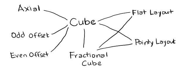
- Cube
- is the canonical coordinate system used for algorithms. I've implemented only one of many variants.
- FractionalCube
- is used to represent non-grid locations. I needed this for line drawing and for pixel to hex conversion.
- Hex
- is the coordinate system used for storage. I've implemented Axial (only one variant) and Offset (even and odd parity).
- Layout
- is used to convert from hexes to screen coordinates for drawing and from screen coordinates to hexes for mouse clicks. I've implemented Pointy and Flat topped hex layouts.
- Point
- is the coordinate system for screen coordinates. This will typically come from your graphics library, but for the generated code I've included a placeholder data structure.
To implement these, I wanted a language that lets me work easily with abstract syntax trees. My usual choices are PLT Scheme (Racket) or ML (OCaml). Scheme is a little nicer for this because it gives me an easy way to define the proto-algorithms using macros so that I don't have to write my own parser. For this particular project though I wanted to run the code generator on the server (to generate all variants and run unit tests on the generated code) and in the browser (to generate custom code based on your preferences). I chose Haxe, an ML-influenced language with the programming features I wanted (tagged unions and pattern matching and macros) and also the platform features I wanted (can run on the server but can also generate Javascript to run in the browser). Also, my hex grid code is already written in Haxe, so I was hoping to be able to reuse it for the proto-algorithms.
I wrote code that reads function definitions and outputs code to generate the syntax trees for those definitions. For example, if I write x+3, Haxe will give me something like EBinOp(OpAdd, CIdent("x"), CInt(3)). I want to produce something like Add(Name("x"), Int(3)), so I need the macro to return something like ECall(CIdent("Add"), [ECall(CIdent("Name"), [CString("x")]), ECall(CIdent("Int"), [CInt(3)])]). I have code that reads code and generates code that generates code. Scheme/Racket is an ideal language for that kind of thing.
In the process of implementing the proto-algorithm to algorithm compiler, I made some discoveries and realizations:
- My diagrams are written in Javascript, which doesn't have a separate int and float type, but in many languages I need to distinguish these. As a result, I created a type
FractionalCubewith floats that's separate fromCubewith ints.FractionalCubeis used for two main algorithms, pixel to hex and line drawing, and both of those need a helper routine, hex rounding. - I realized that my explanation for pointy vs flat top hexagons is inconsistent. In one section, I claim it's a rotation of 30°. In other sections, I claim the algorithms are simply different. In my underlying code, I often swap x and y. The code is simplest if swapping x and y, or rotating 90°, but the names of axes stay most consistent (q for columns, r for rows) if I rotate by 30°. I don't know which I should use.
- It's also possible to generalize even further, and rotate by any angle. This is less "simple" because it means I need to insert an additional rotation step in a few places, but it's more general. I'm not yet ready to switch to this.
- In the offset grid section, I claim that there are four types, odd-r, even-r, odd-q, and even-q. However, if pointy vs flat is a swapping of x and y (instead of a rotation by 30°), then odd-r and odd-q are related by swapping both x/y and q/r. Much simpler! This means there are really only two offset types, odd-parity and even-parity.
- It's also possible to generalize even further, and say that the offset can be by any odd number. The odd-parity (odd-r and odd-q) variants become an offset by -1 and the even-parity (even-r and even-q) variants become an offset by +1. This simplifies even more. I'm not yet ready to switch to this.
- The remaining grid variants involve renaming the axes and changing their signs. I'd like to implement this at some point, but I don't know if it's really worth it.
- Cube and Axial coordinate systems are pretty much the same, except Cube explicitly stores the third coordinate, and Axial calculates it when needed. It might make sense to merge the two, and call the axes q, r, s. I need to think about this more.
- Offset and Axial share much less code than I had expected. One of the algorithms (
hex_direction) doesn't work with offset grids, and two of the algorithms (hex_neighborandhex_add) have different implementations for offset and axial. If I merge Cube and Axial, then Offset would be its own thing. I need to think about this more. - It's pretty clean to separate out anything involving the screen from everything else, which only involves the grid. This means variants like the y-axis pointing up or down go away, except for a small part of the code. Screen transformations include translations (centering hex 0,0 at x,y other than 0,0), scaling (setting the size of the hex, including hexes that are taller or shorter than usual), rotations (primarily 90° but any angle is possible), and transformations for isometric views.
I started this project thinking I would need to generate lots of algorithms. I thought the algorithm generation step would take the most work, and the code generation step would be relatively easy. I ended up spending a lot more time thinking about how to represent the modules. I don't actually need to generate lots of algorithms. Instead, I am considering changing the page to use a simpler approach:
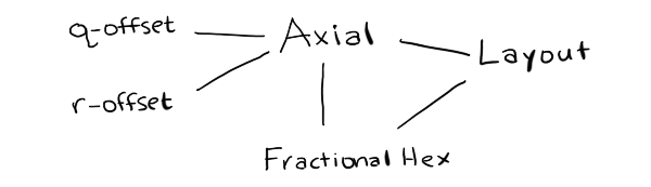
If I do that, it will be a major change to the hex grid guide.
In the next post I'll talk about the code generation.
Hex grids: procedurally generating code #
I've been questioning some of my approach to writing tutorials. Most of the time I provide algorithms, math, and pseudocode but not runnable code. Part of the reason is that I've been on so many platforms and languages in the past, and I don't want to spend time on things that are useful today but not five years from now. Part of the reason is that I learn better by studying pseudocode and producing runnable code. And part of the reason is that many of the topics I cover (pathfinding, simulation, AI) aren't really about code, but about techniques that are useful when writing code. Most of it has to be adapted for each game.
Hex grids are different though. There's not as much to be learned by studying the code; I think most of it is learned through the diagrams and explanations. Adaptation is sometimes tricky, and I don't want you spending your time on trivial bugs like missing a negative sign. So I decided to try, for this one page, providing some useful code.
Which language? Which platform? Which of the 70+ grid types? How many combinations of these can I practically provide code for?
Well, of course, the solution is procedural generation, right? Right??
I attempted to procedurally generate downloadable libraries to handle hex grids.
The plan was:
- Write some "proto-algorithms" that could work with any geometry.
- Ask the reader about the geometry of hex grids being used.
- Mix the "proto-algorithm" with a description of the geometry, generating algorithms in some abstract format.
- Ask the reader about the programming language and style.
- Turn the generated algorithms into downloadable code.
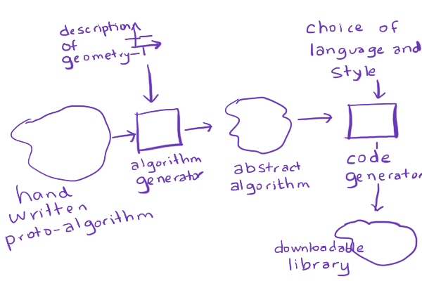
For example, I would write a "proto-algorithm" by hand for hex distances:
/* Distance between two hexes */
function hex_distance(a, b) {
    var ac = cube(a);
    var bc = cube(b);
    var dx = ac.x - bc.x;
    var dy = ac.y - bc.y;
    var dz = ac.z - bc.z;
    return abs(dx) + abs(dy) + abs(dz);
}
Let's say that the reader uses an axial coordinate system where x=q, y=-r, z=r-q. This is different from the one I use in my hex grid guide. So if you wanted to take the hex distance algorithm from my page and adapt it for this coordinate system, it'd be a little tricky, with some renaming and sign flipping. I should be able to generate it instead, by inlining the cube conversion:
function hex_distance(a, b) {
    var ax = a.q;
    var ay = -a.r;
    var az = a.r - a.q;
    var bx = b.q;
    var by = -b.r;
    var bz = b.r - b.q;
    var dx = ax - bx;
    var dy = ay - by;
    var dz = az - bz;
    return abs(dx) + abs(dy) + abs(dz);
}
and then simplifying that code:
function hex_distance(a, b) {
    var dx = a.q - b.q;
    var dy = -a.r + b.r;
    var dz = a.r - a.q - b.r + b.q;
    return abs(dx) + abs(dy) + abs(dz);
}
and simplifying more:
function hex_distance(a, b) {
    return abs(a.q - b.q) + abs(b.r - a.r) + abs(a.r - a.q - b.r + b.q);
}
Then if the reader says, I want Java code for this, with three space indentation, I could convert this abstract format into Java code:
public abstract class AbstractSpringBeanFactoryProxy { ... }
No, no, not like that! Sorry. ;-) How about this:
public class Hex {
   public int q, r;
   ...
   /**
    * Distance between two hexes
    */
   public static distance(Hex a, Hex b) {
      return Math.abs(a.q - b.q) + Math.abs(b.r - a.r) + Math.abs(a.r - a.q - b.r + b.q);
   }
   ...
}
Wouldn't that be cool? Custom-built algorithms for your choice of hex grid, in your choice of language, in your preferred programming style? With comments? And if I'm generating code that could be error-prone, I should have unit tests too, right? And of course I should procedurally generate the unit tests. And if I'm generating unit tests, I should generate all possible grid variants and all possible languages on the server, and compile and run the unit tests, so that I make sure that whichever choices the reader makes, the code will be correct.
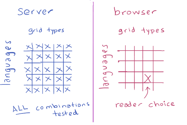
I knew it was a little ambitious, and probably way overkill, but I decided to try anyway.
Well, as expected, I didn't succeed. In the next blog post, I'll describe what happened.
Hex grids: simplifying the variants #
On the original hex grid guide I had claimed there were over 70 variants of hex grids. Most of these turn out to be merely a different choice of axes, either by renaming them or by negating the sign. Here are some variants of offset coordinates:

And here are some variants of axial coordinates:

Axial and Cube are really the same, except Cubes explicitly store the third coordinate and in Axial we calculate it in the accessor, when needed.

Why would you want some of the other labelings? If I use an alternate labeling of offset coordinates, I can rotate the entire grid from pointy top to flat top and back:

This simplifies the math. It means I no longer need to treat pointy and flat top hexes separately, but instead I can focus on just a few basic grid types (cube, axial, even offset, odd offset) and then produce the pointy and flat top from those. I can further simplify by merging axial and cube together. I don't yet know if I want to do that. Can I merge even and odd offset? Yes, probably, but I think I won't right now.

Pointy top vs Flat top is a rotation. I had originally claimed it was a rotation of 30° but it is simpler to think of it as a rotation of 90°. It's even simpler to think of it as a permutation of x,y into y,x (renaming axes). There are also several coordinate systems that I don't cover on the page, and don't plan to anytime soon. However I might add a supplemental page that describes them.
I believe the new descriptions of coordinate systems will be simpler than the previous ones. However, they're also different, and I worry about changing the system that I've described in some incompatible way.
- Should I unify Axial and Cube?
- Even if I don't, should I rename Cube's coordinates from x,y,z to q,r,s? That way they match up more closely, and Cube is no longer confused with cartesian coordinates.
- Should I unify even Offset (even-q, even-r) and odd Offset (odd-q, odd-r)? I think the math is slightly uglier but it'd work just fine.
- Should I try to support all possible axis assignments, or just some "canonical" ones like I do now?
- Should I try to preserve the specific choices of axes on the current page, or choose the ones that make things simpler?
Update: [2015-03-28] I'm no longer convinced that swapping x,y is the easiest way to deal with pointy vs flat top. It's the simplest implementation, but it causes "q" and "r" to no longer correspond to "column" and "row", and I think it might be worth preserving that mnemonic. A 90° rotation is nice to implement too but I think the 30° rotation best preserves q/r.
Optimizing A* for grid maps #
One thing that annoys me about my own A* pages is that they use grids for the examples. A* is not restricted to grids. A* works on any directed graph. A* on uniform grids is often slow, so people have come up with various ways to make the algorithm faster. I feel like the "right" thing to do is not to change the algorithm but to change the data.
Graph search is used when you want to make "global" decisions that involve potentially analyzing large parts of the map. You look ahead all the way to the end before you can decide anything. It's a waste to use it on "local" decisions that you can make without looking far ahead. Suppose you have this game map (from Baldur's Gate):

What's the easiest thing to do? Make each tile into a graph node:

This is a fine solution, but A* will take a while to find the paths. There are a lot of nodes to visit. Some algorithms will make A* faster by using a cheaper way to visit the nodes. However, it's even faster if you skip most nodes altogether. For any path on this map, almost all of steps can be decided locally, by just following a straight line. There's no need to give those nodes to A*. Instead of making every tile into a pathfinding graph node, give a smaller graph to A*:

You'll need to annotate the map with this graph, either manually in a level editor or automatically with a preprocessing algorithm. A* will run much faster on the tiny graph than the dense grid graph. If you're looking to optimize A* on a grid, consider changing the data before you consider changing the algorithm. Navigation meshes, visibility graphs, and hierarchical approaches are all worth a look.
I have a little more written here and here, but one of these days I will update my pages to put less emphasis on grids.
Labels: grids , pathfinding
Notes on line drawing on grid maps #
I'm not a fan of Bresenham's line drawing algorithm. I know, it's fast, and sometimes you want to complicate the code for speed. But these days, fast line drawing is going to be done by the graphics library. I only need line drawing for analyzing grid maps in my game. Line drawing performance isn't critical anymore for me, so I prefer using a much simpler algorithm. I decided to write up my notes about that.
I don't like that Bresenham's algorithm has separate cases for 8 octants. You can collapse some of these with a series of if statements, but I prefer interpolation, where there aren't different cases. I don't like that some presentations of Bresenham's algorithm handle only one octant and leave the rest as an exercise to the reader. I don't like that some implementations of Bresenham's swap the endpoints, which is fine for drawing lines, but not as good for game algorithms such as moving an arrow from the player's bow to the enemy orc.
I like that the linear interpolation algorithm reuses concepts that are useful for other parts of my games. I also like that the same line drawing algorithm works on 3d grids and hex grids. I like that interpolation as a concept can be extended to angles, times, spherical rotations, and other things. I like that linear interpolation leads to non-linear interpolation, often used for animation.
Interpolation is both more general and simpler than Bresenham's algorithm. I use it for lots of other things, so I use it for line drawing too, instead of using a different specialized algorithm for line drawing.
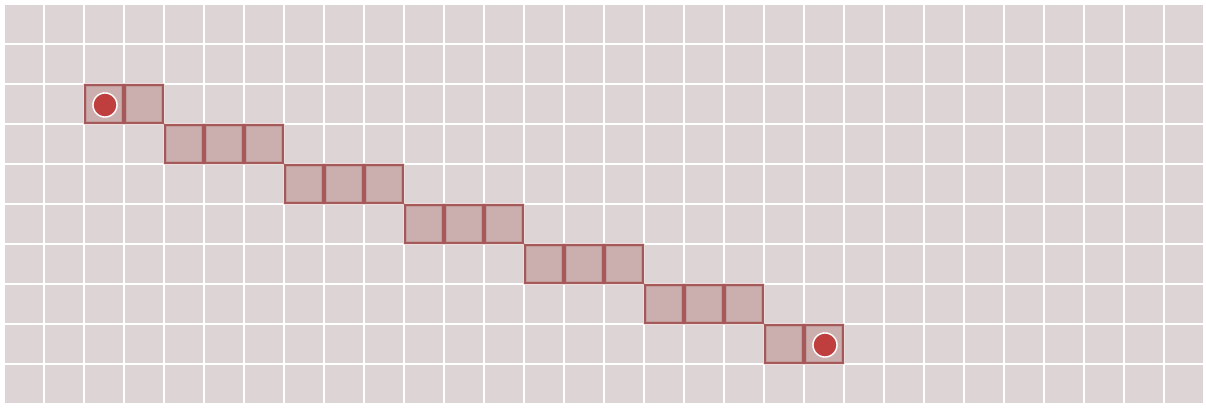
I wrote up my notes about line drawing using linear interpolation
What went right?
- Org-mode
I've been trying out emacs org-mode for some of my smaller articles. It worked really well in this case. I used org-babel, which lets me embed source code along with the article text. For each block I can choose whether it gets output as javascript, in the html, or both. The code I present is the same code used to power the diagrams (for the most part).
You can see the org-mode source here.
- Diagram class
I wrote a small diagram class that let me turn on various optional features. I then instantiated it for each of the diagrams on the page, enabling different features for each.
- All the diagrams show a grid.
- Some diagrams show a single interpolation point, controlled through a number control on the page.
- Some diagrams show many interpolation points. The number of points is either calculated automatically or controlled through a number control on the page.
- Some diagrams show a "track" that contains the interpolation points
- Some diagrams show draggable endpoints. In the end, all of them did, but during development I wasn't sure if I'd do that.
I also have various hacks that aren't cleanly put into the diagram class. That's ok. I'm trying to make a pretty page, not make pretty code. I make pretty code only if it helps me make the pretty page more quickly. Unlike most software projects, there's not much maintenance over time, so that up-front investment usually doesn't pay off.
- Draggable numbers
I have a draggable number library that I haven't shared yet, but I've used for a few unfinished projects. I used it here. It's like Bret Victor's Tangle but uses D3 instead of MooTools.
- Draggable markers
I used draggable markers that I explained here and they worked pretty well.
What went wrong?
Scope creep was the biggest problem. It's just line drawing. I thought it'd be quick to write up. But I kept thinking of more things I wanted to add.
- Scope - algorithms
My original plan was to explain two line drawing algorithms, but the more I worked on those, the more variants I started finding. I added the supercover line drawing, but I had several more I wanted to add when I realized … I should just stop and publish the article.
- Scope - topics
As I got into interpolation for 2d grid lines, I realized that other aspects of interpolation are pretty cool too: non-linear interpolation (used in animation "tweens"), hex grid lines, 3d grid lines, interpolation in color space.
I even had written interactive demos for interpolation in different color spaces, comparing RGB, HSL, HCL, Lab, but I ripped it all out when I realized I was going way outside the scope of the page.
- Scope - interactivity
Bret Victor had talked about how the technology of the printing press led us to separate images and text, and we keep doing that on the web even though we don't use moveable type anymore. That made me wonder what kinds of things I'd like to do for explanations that break out of my standard format of text separated from diagrams.
What first came to mind was what I do on paper: I make arrows that point from one thing to another thing, even if it's not in the same "box".
I started implementing this, and was quite happy with what I had, but decided it wasn't worth the effort for this article. I ripped it out, and will try it again for another article. It was a neat effect that I don't see people using. Try mousing over this paragraph, and you'll see an arrow pointing back to the section heading:
In the end…
I needed this small project. I've been sort of stuck since September, so this got me going again. I often find that when I'm stuck, I need to do something simpler, and then work my way up again.